
The check almost everyone does before a first case takes four seconds. Connect the fiber, switch on the aiming beam, see a green dot at the far end, and start. It feels like a complete verification because it produces a clear pass/fail answer, and the answer is usually pass.
It is also the check that a manufacturer’s own field safety notice tells you not to trust. In a 2025 medical device correction for a superpulsed thulium system, the manufacturer required users to verify each newly connected fiber with the aiming beam, and then added one sentence that undermines the four-second version: a faint green light may still be visible at the fiber tip even when that fiber is damaged. If the light can be present at the far end of a broken fiber, then “I can see the dot” is not a criterion. It is a coincidence.
That single sentence reframes the whole exercise. You are not checking whether light comes out. You are checking where else it comes out, and what shape it makes when it arrives. Those are two different tests, and only one of them can be passed by accident.
What a setup checklist is actually for
The distinction that matters is between an inspection and a decision procedure.
An inspection ends in an opinion: it looks fine, it looks a bit dark at the tip, it looks like last time. That is how most experienced operators work, and it holds up until the day the judgment is wrong, because nothing in the process forced the wrongness to become visible.
A decision procedure is arranged the other way around. Every step carries a stated observation and a stated action, and the action is usually to stop. There is no step where you weigh evidence. That sounds mechanical, deliberately so: a checklist is not there to replace skill but to remove the class of failures skill cannot catch — the ones that look normal.
The physics of why a tip degrades is a separate article. What follows is only what you do about it on the tray.
One design rule runs through all six steps below. Each one is built to fail in a safe direction: if you misread it, you discard a good fiber. That is the acceptable error. The unacceptable error — using a damaged fiber because it passed a check it should have failed — is the one the whole sequence is arranged to prevent.
The pouch, before anything is opened
Five things are on the label, and you are not reading them for interest.
- Model and core size — against what your console and handpiece are configured for
- Lot number — the only traceability you will have if something goes wrong later
- Expiry date — sterility has a clock, and a fiber that sat in a store cupboard is not the same as one that did not
- Sterilization method — because it tells you which process the package was validated for
- The single-use symbol — the crossed-out 2, as defined in ISO 15223-1 and ISO 7000-1051
Then check the pouch itself. Not the fiber — the pouch. A breach in the sterile barrier is the one failure in this entire list that you can detect before the patient is in the room, and that timing matters more than the failure does. EU MDR Annex I §23.4 requires the instructions for use to state an explicit procedure for damaged sterile packaging, precisely because this is a foreseeable event rather than an edge case. Read that procedure rather than improvising one.
The reason to spend time here is arithmetic, not caution. A swap made now costs one fiber. The same swap made forty minutes in costs a fiber, an interruption, a re-drape and whatever the delay does to the case. It is the cheapest decision you will make all day, and the way it gets skipped is that the tear looks minor.
Three matches, not one
Compatibility is not a single question, and the three parts fail independently.
| What has to match | The criterion | The non-criterion |
| Geometry | Core size and connector type are the ones the console and handpiece are specified for | “The connector screws on” — a physically compatible connector can still be optically wrong |
| Wavelength | The fiber’s transmission window covers the wavelength you will actually fire | “It worked with the other laser” |
| Power | Your setting is inside the fiber’s stated maximum | “It is the same core size as the last one” |
Power is the one people treat as a formality, and it has the least headroom. Ratings are specific to a fiber and its build. A published example makes the spread concrete: one manufacturer’s range is rated at 30 W for its 200 µm fiber, 50 W for 273 µm, and 120 W for 365 µm and above. Those are that manufacturer’s numbers for its own fibers, quoted only to show the shape of the thing — the rating is not transferable between products, and the number that governs your case is the one on the fiber in your hand and on the bare fiber specification it belongs to.
Connection: three mechanical rules and one criterion
Every step in this section is a mechanical action, and this is the part of a first case that most often goes wrong. Nothing here involves physics or judgment. It is all hands.
Connect with the laser in STANDBY or OFF. The published instructions for delivery fibers state this directly, and the reason is that the connector is being mated while the far end of the fiber is pointing at something you have not yet chosen. Bringing a fiber into alignment on a live system is a decision made in the wrong order.
Remove the protective cap without gripping the strain relief or the fiber body. Hold the connector. The same rule governs unpacking: pull the fiber out of its hoop by the connector rather than by the fiber. The strain relief is a transition, not a handle, and it is the one region where the fiber is both constrained and unsupported.
Finger-tighten until the interlock releases. Note what the criterion is. Not “tight”, not “tight enough” — the point at which the connector’s interlock releases and reports itself as seated. That is a binary signal the hardware produces. A partial seat looks identical from the outside and couples unpredictably.
Inspect the input face at magnification before mating. The published instruction specifies 20× and a wipe with a sterile tissue if contamination is present. The input face is where the console’s energy enters the fiber, and anything on it becomes a heat source at full power.
The full length — the step that the habit skips
This is the counterintuitive one, and it is the reason this article exists.
Clinical habit checks the tip. The tip is where the energy comes out, so it is where the damage is assumed to be. But in the largest published body of evidence on this question, the tip is not where the failures are. The 2025 correction referenced above reports, since the system’s 2019 launch, 175 reportable malfunctions and two serious injuries — one a fiber break that burned the user’s hand, the other a single-use fiber that ignited and delayed a procedure. The investigation’s preliminary finding locates the cause in a fiber break either at the strain relief or anywhere along the length of the fiber. Not at the output face.
The mechanism explains why a break in an innocuous-looking place is a hazard rather than an inconvenience: a break in the core disperses energy at that point. The fiber stops being a pipe and becomes an emitter, and the energy leaves into the coating, the jacket and whatever is beside them.
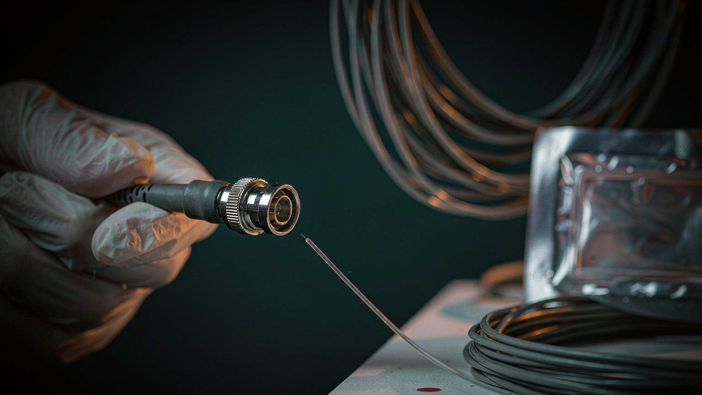
Which gives the aiming beam a second job, and it is the job that actually works. Sweep the aiming beam and look for green light anywhere other than the distal tip — along the length, or inside the strain relief where it enters the connector. That is a longer job than it sounds, because a standard 3 m bare fiber is three meters of jacketed fiber to walk your eye down, and the break can be anywhere on it. The notice’s wording is unambiguous: green light appearing at any portion other than the distal tip means the fiber is damaged, replace it. And note the corollary, which is the sentence quoted at the top of this article: light at the tip does not cancel that finding. You are looking for an extra source of light, not for the absence of the expected one.
One practical consequence: the strain relief has to be inspected visually as well as optically, because a near-complete break can show as a mark or a kink before it shows as light.
The spot: read the shape, not the brightness
Now the tip, and here the check does become a judgment — but a much more precise one than “is it bright”.
Hold the tip about 5 cm from a light surface and look at the spot. Published criteria from a delivery fiber’s instructions for use give both sides of the line:
Acceptable — a perfect circle with a dark center; or a circle with a light halo around it. Not acceptable — a circle with a thick halo; an elliptical or otherwise non-circular pattern; a spot with a comet tail extending from one edge; sharp striations radiating from the center.
Read that list twice, because two of its entries are the same feature at different amounts. A thin halo is acceptable and a thick halo is not. The halo is stray light leaving the tip at a wider angle than the guided beam, and a little of it is normal. What changes the verdict is how much of it there is, which is a proxy for how much of the energy is no longer travelling down the core. The judgment being asked of you is not whether you can see the halo. It is whether the halo has started to dominate.
A comet tail is a different phenomenon and an easier call: a streak extending from one edge of the spot means the emitting face is fractured asymmetrically, and there is no version of that finding you continue with. The same criterion appears in the veterinary literature on retained fiber fragments, and in dental laser handpiece guidance, where an irregularly cleaved fiber is identified by exactly this signature. Three independent sources, one discriminator.
Two supporting observations while you are at the tip:
- Look at the tip at magnification and check the hard polymer coating, not just the glass. The plane-polished end face is the one part of a bare fiber with no buffer over it, so a coating that is missing, scratched or lifted leaves it unsupported — and published instructions note that a damaged coating can mean a coating fragment detaches during use.
- Check eye protection for the wavelength you are actually firing. Eyewear is rated by wavelength and optical density and is not interchangeable between lasers. ANSI Z136.3-2024 requires the eyewear to be labeled with the wavelength range and OD it provides, and adds that approved and tested eyewear should be used for treatments on the face and neck. If your laser safety goggles are labeled in nm, this step closes in a glance; if they are labeled “laser”, it does not.
The re-entry conditions
A checklist that runs once is incomplete. The most useful part of the 2025 notice is arguably the trigger list, because it defines when the setup check becomes a during-case check: the fiber has been stepped on, pulled, left lying in a vulnerable position, kinked, tightly coiled, or pinched.
The procedure the notice specifies is a good template for any system. Put the console in STANDBY. Confirm the aiming beam is on — intensity is adjustable, and a bright green is easier to read than a faint one. Then repeat the step-4 inspection, from the beginning, over the whole length. Not a glance at the tip.
The one-sentence version: a fiber that has been through any of those six events does not have a known state any more, whatever it looks like. Re-verify rather than re-assess.
Re-cleaving: the thing this checklist does not ask you to do
A fiber cleaver and a fiber stripper belong in the same conversation, and the honest framing is uncomfortable.
Re-creating an end face in the middle of a case changes three things at once. The flatness of the face, because a hand cleave is a scribe-and-break rather than the geometry a production process produces — a fiber cleaver produces its face by scoring and breaking the fiber in a single motion, so what comes out is a controlled fracture whose angle is set by the tool and the hand holding it. The length of exposed fiber ahead of the coating, which determines whether the fiber will still pass a working channel without catching. And the fiber’s identity — it stops being a device whose state is known and becomes one whose state is unknown, which is a meaningful downgrade when the next step is a patient.
So the correct role for on-site re-cleaving is a fallback, not a routine. It exists because a fiber that has been re-worked is generally preferable to a fiber that is known to be broken. Where manufacturers publish it as an option, they pair a stripper with a scoring wafer and specify the technique; where they do not, the IFU’s answer to a damaged tip is replacement. If a case could be salvaged by re-cleaving but a replacement fiber is within reach, the re-cleave is not the cheaper option — it is the one with unverified geometry.
That also settles where this checklist sits relative to reusing fibers at all. A reusable fiber, where a manufacturer offers one and publishes a reuse count for it, is a device with a bounded number written into its instructions — one published reusable line, for example, states reuse up to five times and expressly not indefinite reuse. That is a specification. Reprocessing a device supplied as single-use is a different question, governed by the manufacturer’s instructions and by regulation rather than by whether it still looks intact. Where the IFU gives a procedure, follow it; where it does not, the default is replacement.