
The morning list has a turbinate reduction on it: 940 nm, 10 W, a bare fiber held a few millimetres off the mucosa while the surgeon waits for it to blanch. The afternoon list has a tonsillotomy: 1470 nm, 15 W, the same fiber now pressed flat against tissue, cutting. Both op notes will read “diode laser”. Neither will record the thing that actually differs — that somewhere between the two cases the fiber stops being a piece of optics and becomes a heated object, and that the physics of what it does to tissue changes completely at that moment.
Pick any ENT theater and you will find one fiber range being asked to cover both jobs. The catalogues treat that as a convenience. It is closer to a constraint, because the three decisions in this article — core diameter, contact versus non-contact, and how the tip is prepared — are not three independent choices. They are three ways of setting one variable: how much energy arrives per unit area, and how long it stays coherent when it gets there.
Get that variable wrong in a nose and you get crusting that lasts a month. Get it wrong in an airway and the fiber is the thing that fails. This piece is about how to hold the three dials together, and what the current evidence actually supports on each.
The number that is not on the datasheet
Fiber datasheets list core diameter, numerical aperture, connector and maximum power. What they cannot list is irradiance, because irradiance depends on the power you dial in — and on nothing else except the area of the core face.
| Core diameter | Face area | Irradiance at 10 W | Relative to 600 µm |
| 200 µm | 3.1 × 10⁻⁴ cm² | ≈ 31,800 W/cm² | 9.0 × |
| 400 µm | 1.26 × 10⁻³ cm² | ≈ 7,960 W/cm² | 2.25 × |
| 600 µm | 2.83 × 10⁻³ cm² | ≈ 3,540 W/cm² | 1 × |
| 800 µm | 5.03 × 10⁻³ cm² | ≈ 1,990 W/cm² | 0.56 × |
| 1000 µm | 7.85 × 10⁻³ cm² | ≈ 1,270 W/cm² | 0.36 × |
Read the third column and the whole selection problem becomes visible. Ten watts is a different physical event through each of these fibers. Moving from 600 µm to 400 µm leaves the console untouched and multiplies the density at the tip by 2.25; going the other way, from 400 µm to 600 µm, halves it. The power setting is not the dose. The core is half the dose, and the console never mentions it.
This is not a theoretical concern in ENT, because the field’s most common fiber is also its most forgiving one. The 400–600 µm range appears again and again in the rhinology literature precisely because those two cores bracket the useful irradiance window for mucosal work at 940 and 1470 nm. Step down to 200 µm and you have the density you need for a stapes footplate or a tight flexible channel, but also a fiber that will char and burn back the moment it dwells on a turbinate.
Core diameter in a nose: why 400 and 600 dominate
There is a useful asymmetry hidden in the ENT literature: the two most-cited turbinate protocols use the same core for two different laser types, and the difference between them is not the diameter.
An early endonasal study using a fiber-guidance instrument treated 30 patients with a 940 nm diode through a 400 µm soft-bending plastic-clad silica fiber at 8–10 W continuous wave, delivering 600–1,000 J per turbinate in three to five applications along the inferior turbinate from posterior to anterior. Twenty more patients in the same study were treated with a Ho:YAG at 2080 nm through a 400 µm hard-bending low-OH quartz fiber — same core diameter, different cladding chemistry, because 940 nm travels happily through plastic-clad silica while 2.1 µm does not. The light loss at 45° of deflection through that guidance instrument was measured at under 10% across 630–2100 nm, and the polished flat tip stayed intact through the working channel. About 75% of those patients reported improved nasal breathing at 15 months.
Two lessons come out of that design, and neither is about wattage. First, core diameter and cladding type are separate specifications, and the second one is wavelength-locked: a 400 µm fiber is not a 400 µm fiber if one is plastic-clad silica and the other is low-OH quartz. Second, when the fiber is routed through a guidance instrument and deflected, the delivery geometry — not the fiber alone — sets how much light arrives. That point comes back later.
The power gradient that has since become the de facto reference across wavelengths is worth writing down, because it is the clearest statement of how wavelength and irradiance trade against each other in the nose: for non-contact turbinate work with a flexible silica bare fiber of 400–600 µm core, the published settings are 8–12 W at 940 nm, 4–5 W at 1470 nm, and 2–4 W at 1940 nm (Sroka et al., J Biomed Opt 2015). Three wavelengths, three very different wattages, one similar clinical endpoint. The wattage changed by a factor of four; what stayed roughly constant was the irradiance at the mucosa. That is the whole argument of this article compressed into one sentence.
Where do the other cores belong?
- 200 µm — stapes and footplate work, glottis and subglottic lesions where a fine flexible fiber must reach a small target, and any application where the density has to come from a small area rather than a high wattage. Its liability is proportional: same core, nine times the density of a 600 µm fiber, and the least thermal mass to shed heat.
- 400 µm — the default for non-contact mucosal work, and the smallest core that still tolerates a sensible duty cycle at turbinate powers.
- 600 µm — the contact cutting core. The intra-individual randomised tonsillotomy comparison that put a 1470 nm diode in contact mode at 15 W against a CO₂ laser ran at 2.7 versus 4.9 minutes with less intraoperative bleeding and no difference in post-operative pain. Fifteen watts through 600 µm is about 5,300 W/cm² — hot enough to cut, not so concentrated that the tip instantly vaporises and screens the tissue behind it. Through 400 µm the same 15 W is 11,900 W/cm², and burn-back becomes the limiting factor rather than the tissue effect.
- 800 and 1000 µm — power handling and gentleness. Rarely the right answer in ENT, occasionally the right answer for high-power coagulation through a straight, rigid delivery.
The practical form of all this: if you find yourself reaching for the power dial to change the effect, you are probably trying to fix a core-diameter decision with the wrong control.
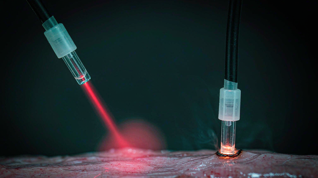
Contact mode is a different device made from the same fiber
Touch a fiber tip to tissue and the absorber changes. In non-contact mode the chromophore is water and haemoglobin in the mucosa, and the fiber’s job is to keep the beam clean until it gets there. In contact mode the chromophore is the tip itself: a thin carbonised layer forms on the glass, absorbs the beam, reaches vaporisation temperature, and starts cutting. The fiber has become a thermal scalpel.
The ENT literature is unusually explicit about this, and it uses the vocabulary ophthalmologists and urologists use for the same phenomenon. Krespi’s group designed the posterior nasal nerve procedure around an uninitiated tip — clear glass, no carbon layer — and delivered it in non-contact mode, because an initiated tip would have produced the carbonisation, reduced penetration and vaporisation they explicitly did not want. The distinction between an initiated (black) and uninitiated (clear) tip is a real physical one: it is the difference between a fiber that coagulates and a fiber that cuts, drawn from the same 400 µm core at the same 5 W.
Three things follow, and the third is the one that costs people cases.
- Initiation is one-way. Once the tip has carbonised, you cannot return to clean non-contact coagulation with it. The carbon layer will keep absorbing. If a case needs both modes, it needs either two fibers or a re-prepare in the middle.
- In contact cutting, the carbon layer is the mechanism, not a fault. This is why the maintenance guidance for contact lasers reads so differently from the guidance for coagulation. A contaminated tip producing intense vaporisation with a surrounding coagulation zone may be exactly the intended effect — the question is not whether carbonisation happened, but whether it was intended and stable.
- The failure mode of contact work in ENT is not depth, it is adhesion and burn-back. A tip that dwells on tissue builds a deposit, the deposit makes the tip stick, and a stuck tip under traction is how fibers break and tips detach. This is the mechanism sitting behind the ENT adverse-event data, and it is worth looking at directly.
The FDA’s device experience database, filtered for upper-airway laser surgery across a decade, produced 62 reports containing 95 events: 42.1% adverse events to patients, 2.1% to operators, and 55.8% device malfunctions. Within the malfunctions, fiber break accounted for 49.1% and flare for 22.6%. Within the patient events, dislodgement of the laser fiber in the airway was the single most common, at 57.5% (Tong et al., Otolaryngol Head Neck Surg 2021). The two operator injuries in the whole dataset were both eye exposure through unfiltered microscope lenses.
Sit with that split for a second. The most common harm to the patient in airway laser surgery is a fiber that moved. The most common device failure is a fiber that broke. The consumable is not a peripheral in this specialty — it is the component that fails most often, and most of the failure happens at the tip and at the fixation, not in the middle of the fiber.