
Two spec sheets arrive for what is nominally the same product: a 400 µm core, 0.22 NA, low-OH all-silica delivery fiber, three meters, terminated. Core diameter matches. NA matches. Both are step-index multimode. Both quote an attenuation figure in dB/km that looks reasonable next to the rest of the market. One of them runs all day at 120 W. The other one discolored its connector inside a week.
Neither sheet is dishonest. That is what makes the pair worth studying. Everything on both documents is true, and neither document contains the number that would have separated them, because a delivery fiber specification is not written in watts.
It is written in micrometers, decibels and pascals. Those are the three languages the fiber trade has used since long before anyone pointed a laser into one, and they describe the fiber, the light that fails to arrive, and the glass that might break. Your question — how many watts do I put in, how many come out, and what happens to the difference — is a fourth language, and it is not on the page. It has to be assembled by whoever reads the sheet.
So the skill is not finding the biggest number. It is knowing which physical quantity each line describes, and noticing which quantities are missing.
The sheet is written in three languages, and none of them is watts
Micrometers describe geometry, and there are more of them than beginners expect: core, cladding, coating, buffer, plus a tolerance on each and a core-to-clad offset. Decibels describe what does not arrive. Pascals, or their imperial cousins the kpsi, describe whether the glass survives being handled.
A real high-power delivery fiber datasheet is a good model of the genre. It lists core diameter options across a wide range, an NA with a tolerance and the acceptance angle that follows from it, an attenuation figure at a stated wavelength, a short-term and a long-term minimum bend radius, a proof-test level, jacket and buffer materials, an operating temperature window, and the connector types the manufacturer will fit — along with a length range that can span three orders of magnitude depending on how the customer will use it.
That is a complete, professionally written document, and it still does not answer the only question a laser system owner has. The reason is structural rather than commercial: a spec sheet describes a component, and your question is about a system. The gap between those two things is where field failures live, and the most useful lines on the sheet are the ones that let you predict how wide that gap will be. Our own bare fiber page is laid out the same way, and the same reading rule applies to it.
The headline number is the one that matters least
Attenuation in dB/km is printed first and set in bold, because for most of the fiber industry’s history it was the product. Eighty kilometers of single-mode at 0.2 dB/km loses 16 dB, and that number decides whether a telecom link needs an amplifier. The same unit applied to a delivery fiber behaves completely differently, and the arithmetic is worth doing once so you never have to trust a feeling about it again:
| Case | Calculation | Total loss |
| Telecom single-mode, 80 km at 0.2 dB/km | 0.2 × 80 | 16 dB |
| Delivery fiber, 3 m at 25 dB/km (low-OH, 2100 nm) | 25 × 0.003 | 0.075 dB |
| Delivery fiber, 3 m at 50 dB/km (pessimistic) | 50 × 0.003 | 0.15 dB |
| Delivery fiber, 10 m at 50 dB/km | 50 × 0.01 | 0.5 dB |
The unit hides the length inside it. For a three-meter delivery fiber, the entire glass path contributes less loss than one end face with a deliberate air gap, which sits at roughly 0.29 dB. Read that comparison twice, because it changes what the attenuation line is for. On a delivery fiber, dB/km is not a power-loss figure at all — it is a purity indicator. It screens for OH content, for metallic contamination in the preform, for the material quality that determines whether the core will absorb energy it should be transmitting. It is worth reading, and it is not worth paying a premium for. It also produces the most counter-intuitive conclusion in this whole article: going from a three-meter fiber to a five-meter fiber is, optically, almost free. The length you carry is decided by your reach, not by your loss budget.
And that number was not measured on your fiber
Here is the part that surprises people who assume a specification is a property. Attenuation is measured under defined conditions, and the conditions matter most for exactly the fiber type medical delivery uses. IEC 60793-1-40 defines the methods: the cut-back method as the reference, insertion loss, optical backscattering, and spectral modeling. Its text is unusually blunt about the reason the reference method exists — launching conditions are “of paramount importance”, and for multimode fiber the goal is to avoid filling the fiber with transient high-order modes, so that steady-state conditions are reached. Reaching steady state in a laboratory takes a long dummy fiber, typically a kilometer or more, or a mandrel-wrapped mode filter sized to the core diameter.
A three-meter delivery fiber cannot reach steady state. So the attenuation figure on its datasheet was either measured on a donor spool and inherited, or measured on the short sample under launch conditions that the sheet does not state. Both are legitimate. Neither is a measurement of the object in your hand. And the spread is not small: an underfilled launch reads a lower attenuation than the true value, an overfilled launch reads higher, which is why the field standard for multimode loss measurement, IEC 61280-4-1, exists and why it targets a variation of ±10 % for losses above 1 dB.
None of this makes the number worthless. It makes it a report about a measurement rather than a statement about a thing. A specification without its conditions is a claim, not a specification. When you buy delivery fibers at volume, the useful question is not “what is your attenuation” but “by which method, under which launch condition, on what specimen length, and can the certificate say so” — which is precisely the exchange that OEM partnerships are for. Suppliers who can answer that question in one email are almost always the ones whose next batch matches the first.
The line nobody reads is the one that decides your installation
Minimum bend radius sits low on most datasheets, often in the mechanical section, and it is frequently reduced to a single number by a reader in a hurry. It is two numbers, and taking the smaller one is the single most common specification error in fiber delivery.
| Core / cladding | NA | Short-term bend radius | Long-term bend radius |
| 200 / 230 µm | 0.37 | ≥ 10 mm | ≥ 16 mm |
| 400 / 480 µm | 0.22 | ≥ 35 mm | ≥ 57 mm |
| 940 / 1000 µm | 0.22 | ≥ 73 mm | ≥ 118 mm |
Read the first and third rows together. Same glass family, same step-index multimode construction, same near-Low-OH silica — and a sevenfold spread in the bend radius, driven by nothing except core diameter. This is the least-publicised trade in laser delivery: core diameter buys you alignment tolerance and pays for it in bend radius. A large core is forgiving of a slightly off-center connector and forgiving of a slightly dirty end face, because the tolerance scales with the core. It is not forgiving of a tight loop, because a higher-order mode that a large core supports is far more willing to leak out of a bend. If you have ever wondered why the fiber that solved your coupling problem now discolors inside a scope channel, that is the mechanism, and both halves of it were on two different spec sheets.
It is also the choice you make between the two numerical apertures our bare fiber page carries. A higher-NA fiber accepts a wider cone and tolerates a tighter bend, at the cost of a faster-diverging output beam — so the quieter number on the datasheet is not always the better one for a scope channel.
The two bend numbers exist for a reason that is worth understanding, because it tells you which one is yours. Silica is brittle, and under sustained tensile stress, water molecules at the tip of a microscopic flaw slowly extend it. The industry’s answer is a proof test during manufacture, and the accepted guidance is that a sustained load should stay below roughly 20 % of the proof-test stress. With the usual 0.69 GPa (100 kpsi) screening level, that puts the long-term limit around 0.14 GPa. Bending a 125 µm fiber to a 30 mm radius already puts roughly 0.15 GPa on its outer surface; at a 10 mm radius it is roughly 0.45 GPa. The derivation is mechanical rather than optical, which is why the short-term figure is a handling tolerance and the long-term figure is a lifetime limit.
For a delivery fiber, this distinction carries more weight than it does for any patch cord. The bend a delivery fiber lives in is not a one-time install radius with a cable clamp holding it. It is the working channel of an endoscope, the loop a handpiece makes on the field, the coil in a storage tray that someone straightened by pulling. Every one of those is a long-term bend, and some of them flex. Design the routing to the long-term number, then add margin for the person who will repack the tray.
The two numbers that describe strength, and the mistake of mixing them
Proof test and tensile strength are the pair most often misread, and the error is a factor of six in the direction of pessimism, or of false confidence, depending on which way you read it.
Proof test is a screening threshold. Every meter of fiber is pulled to a defined stress during manufacture, typically 100 kpsi or 0.69 GPa, which on a 125 µm cladding is about 8.5 N. Anything weak enough to fail at that load breaks in the factory instead of in your case. It is a floor, not a rating. Actual break strength sits far higher — of the order of 4 to 5 GPa for pristine fiber, several times the screening level — and it is reported as a distribution rather than a single number, because glass strength is statistical.
The practical consequence matters more than the terminology. A proof test describes the glass with its coating intact. Strip that coating — which is exactly what happens when a fiber is prepared for a procedure — and the strength you then own is the strength you left. No line on any spec sheet covers that moment, which is why handling discipline is a process question rather than a purchasing one.
The number that should be on the sheet, and isn’t: watts
Now to the missing language. A power rating is the number every buyer looks for, and it is the one that least resembles a fiber property, because it is a property of a chain: power density at the end face, then the termination, then the cooling and the duty cycle.
The first link is geometry and it is dull arithmetic. A 400 µm core has four times the area of a 200 µm core, so at the same power density in W/cm² it carries four times the power. That is why core diameter and power handling travel together in every catalog table, and why a vendor can publish a table of computed maximum powers that runs from hundreds of watts at a small core to tens of kilowatts at a large one.
The second link is where those tables stop being true, and it is worth stating plainly: an ideal-end-face calculation for a 400 µm core at 2100 nm lands in the tens of kilowatts, while a real medical delivery assembly built on that same core is specified one or two orders of magnitude lower. Nothing happened to the glass between those two numbers. Everything happened at the termination. Light that misses the core does not politely disappear; it scatters into the ferrule and into the epoxy holding the fiber, where it heats, carbonises and vaporises the adhesive, depositing a residue on the very face it just left. That residue is an absorber, the absorber runs hotter, and the damage walks itself inwards — the classic high-power end-face failure spiral, described in the same terms by every serious photonics house that writes about it. The fix is architectural, not optical: an epoxy-free zone in front of the fiber, so that the first material the stray light meets is air. That is what the air-gap option on a delivery fiber spec line actually means, and it is why two datasheets can quote the same fiber and different watts.
So when you read a power rating, you are reading a statement about an assembly: which ferrule, which adhesive or none, how much metal is behind it, and whether the duty cycle gives heat anywhere to go. The number describes a ceiling on what may be launched into the face. It says nothing at all about what leaves the other end — and that asymmetry is the whole point of the phrase watts in, watts out.
The number you actually want, and how to assemble it
Optical loss is linear and easy: 0.1 dB is 2.3 % of your power, 0.29 dB is 6.5 %, a full decibel is 20.6 %. At 30 W, one decibel is 6.2 watts; at 120 W, it is nearly 25. Useful, and incomplete.
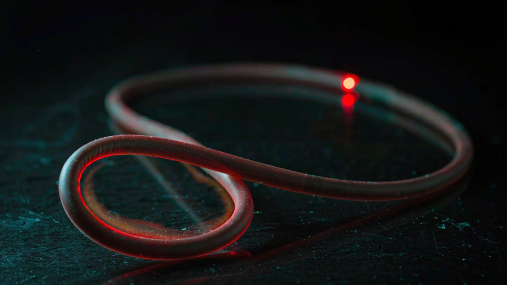
The delivery-fiber-specific twist is that a bend does not merely subtract watts. It puts them, as heat, into the coating. Reliability guidance from the fiber standards community is explicit about this: at bends below roughly 15 mm diameter, coating damage has been observed at optical powers from a few hundred milliwatts upward, because the coating absorbs light that the bend has thrown out of the core. The damage progresses from ageing through pyrolysis to burning, and above roughly 700 °C the glass itself softens. A bend in a delivery fiber is therefore two problems wearing one disguise: it is a loss line and a heat source, wrapped in polymer, sitting inside whatever channel you threaded it through. In a telecom link, a decibel is information. In a delivery fiber, a decibel is heat.