
Radial-tip fibers did not make endovenous ablation work better. Long-term closure series put radial and bare-tip fibers at comparable obliteration rates, and the randomized comparisons that did find a difference found it in postoperative pain and bruising rather than in whether the vein closed. The procedure succeeded either way.
That is the most useful fact in this article, because it says what a tip shape actually is. It is not an upgrade. It is a redistribution of energy you were already delivering — same watts, same wavelength, same joules per centimeter, arriving at the tissue through a different surface. Once you read tip selection that way, the datasheet tables stop being a list of options and become a calculation, and the calculation has one dominant term.
The number that is missing from every tip datasheet
Irradiance is power divided by emitting area, and the emitting area of a fiber tip is not a small correction to the core size — it is the whole story. Using the geometries that sit in our own catalog, with a single 400 µm core at 3 W:
| End face | Emitting area | Irradiance at 3 W | Relative |
| Flat polish, 400 µm core | π/4 × (0.04 cm)² = 1.26 × 10⁻³ cm² | 2,387 W/cm² | 1× |
| 10 mm radial segment on a 400/800 µm fiber | π × 0.08 cm × 1 cm = 0.251 cm² | 12 W/cm² | 1/199 |
| 10 mm diffusing segment, 1.0 mm | π × 0.10 cm × 1 cm = 0.314 cm² | 9.6 W/cm² | 1/249 |
Set that against the specification everyone spends weeks on. Moving from a 200 µm core to a 1000 µm core changes the emitting area by a factor of 25 — π/4 × 1.0² divided by π/4 × 0.2². A single geometry change at the distal face moves it by roughly 200. The last ten millimeters of the fiber are a bigger lever on what the tissue sees than the core diameter, by nearly an order of magnitude. That inversion is the reason this article exists, and nothing on a standard tip datasheet makes it visible, because datasheets list core diameter and shape side by side as if they were comparable choices.
Flat end face: the smallest window, and the only one some wavelengths permit
The flat polish is the baseline, and calling it the cheap option undersells it. It delivers the highest interfacial power density of any geometry — that 2,387 W/cm² figure — which is exactly what a procedure needs when the requirement is to cut, to ablate, or to transfer enough heat into a dense target to do anything at all. The bare fiber line carries it across cores from 200 to 1000 µm, flat or air-gap polished, 30 W rated, with transmission specified from 400 to 2200 nm.
The flat tip is also the only geometry some wavelengths allow. At 2100 nm, water absorbs so strongly that effective tissue penetration is roughly 0.4 mm — an order of magnitude less than at 1470 nm, and far less than at 980 nm. There is no standoff position at that wavelength from which enough energy survives the intervening water to matter. Contact is not a technique preference at 2100 nm, it is the only configuration in which the light arrives, which is why the holmium fiber is built to be brought into contact with the target and why its tip geometry has essentially no freedom to be anything other than flat. A geometry decision that looks like an option at 810 nm is already made for you at 2100 nm, three paragraphs before the surgeon enters the room.
The flat tip’s weakness is not that it wears out faster in any general sense. It is narrower than that, and more interesting. In controlled testing of fibers in still water with no target contact, there was no ablation at all — no tip erosion regardless of power or pulse count, across several fiber brands and core sizes. Erosion appeared only once the fiber touched the stone. Tip degradation at a flat end face is a contact phenomenon, not a power phenomenon. That single observation explains why a tip that behaves perfectly in a water bath can be visibly shortened after one difficult case, and why the failure shows up as a change in geometry rather than as a gradual dimming.
Ball tip: it is a lens, and a lens has a focal length
A ball tip is usually described as a rounded, gentler version of a flat tip. It is more accurate to describe it as a sphere lens welded to the end of the fiber, because that is what the optics do. For a sphere of diameter D and refractive index n, effective focal length is nD/4(n−1) and back focal length is EFL − D/2. A 2 mm N-BK7 ball, for scale, focuses collimated light 1.47 mm from its center and 0.47 mm from its surface. Shrink the ball and the focus moves closer; push the index toward 2 and the back focal length collapses toward zero, which is the design condition where a fiber end can sit in near-contact with the sphere.
The consequence for a medical tip is measurable. A 0.75 mm radius ball increased the effective numerical aperture of a 1.0 mm fiber from 0.5 to 1.2 — roughly tripling the exit cone. But the measurement that matters more is the one usually left out: below about 13 mm of standoff, the ball tip delivered higher central fluence than the same fiber with a flat face, and beyond 13 mm the flat face won. The ball converges before it diverges. In the near field it is a more concentrated emitter than the flat tip it replaces, and only further away does it become the gentler one.
That reframes what a ball tip is for. Its value is not lower power density — a claim that is only true past the crossover distance. Its value is distance tolerance. In a lumen where the working distance cannot be held constant by hand, a ball tip converts a sharply distance-dependent irradiance into a flatter curve, so variability in technique turns into variability in dose rather than variability in perforation risk. Designers have used exactly this property, treating the ball-to-tissue distance as the control variable for the treated area, and clinical work on ball-tipped endovenous fibers has observed that the larger emitting area helps keep energy density below the ablation threshold. Same physics, opposite framing: one application uses the lens to concentrate, another uses it to spread.
Radial: turning a point source into a cylinder
A radial tip produces the largest change in emitting area of the three, because it changes the shape of the emitting surface rather than its finish. A flat or ball face emits from a disc a few hundred micrometers across. A radial fiber emits from the lateral surface of a cylinder: our radial fiber is offered in two distal geometries, ring-unmarked at 400/800 µm and 600/950 µm with a 10 mm glass length, and ring-marked at 400/730 µm and 600/750 µm, all on an SMA 905 interface. Substituting πDL for πd²/4 is what produces the two-orders-of-magnitude step in the table above. The point source becomes a line, and a line spreads over tissue instead of drilling into it.
That is why the closure rates for radial and bare tips came out comparable in the opening paragraph. A radial fiber is not more powerful, it is more evenly distributed, and evenness is a safety property rather than an efficacy one. In a thin-walled tubular structure — a vein wall, an anal canal — the design intent is circumferential and axial uniformity, so that the same energy is delivered along the whole treated length instead of at the single point where the fiber happens to be touching.
Two details are worth keeping separate from the marketing. First, the ring marking is not an optical feature at all; it is a ruler, a visible datum that lets the operator know where the emitting segment starts, which is the difference between “the fiber is in the right place” and “the fiber is probably in the right place.” Second, and less comfortable for tip marketing generally: not every redesigned end face enlarges the emitting area. The tulip geometry, a common alternative to the bare tip in endovenous work, was measured with the same emitting surface area as the bare tip it replaces — it prevents mechanical contact with the wall, and does nothing to power density. Jacketed designs, which actually sheath the emitting tip, do diffuse the beam and lower its power density. Both are sold as “atraumatic tips.” Only one of them changes the number in the table above, and that difference is visible only if you are comparing emitting areas rather than tip names.
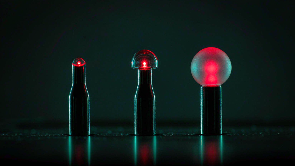
What the controlled comparison found
The cleanest side-by-side of tip geometries comes from a systematic eight-fiber study of soft-tissue ablation at 1064 nm, which compared core diameters, numerical apertures and tip geometries against one another under identical conditions rather than across published papers.
Flat tips with large cores and high NA produced the greatest axial heating and the largest ablation volumes — and then stopped improving. Beyond about 7 W the lesion volume saturated, because heat diffusion into the surrounding tissue and surface carbonization became the limiting factors rather than delivered energy. Carbonization matters more than it sounds: the carbonized layer both absorbs strongly and blocks transmission to the tissue behind it, so growth of the lesion flattens out precisely when the operator increases power.
Radial and spherical tips behaved differently in two ways that matter for selection. Their initial temperature rise was slower, consistent with the reduced power density at the interface, and their lesions were more isotropic — closer to round in cross-section, with a better width-to-length ratio and less longitudinal extension. Interestingly, the ball geometry produced the most uniform lesions of the set and among the largest absolute dimensions, which is a good illustration of the previous section: a diffuse emitter can still create a large lesion, because it avoids the carbonization that caps the flat tip’s growth.
The wider mechanism ladder explains the ordering. Above roughly 60 °C protein denaturation and coagulative necrosis set in; approaching 100 °C, water vaporization becomes the dominant energy sink and limits further temperature rise in adjacent tissue; continued irradiation dehydrates and then carbonizes, transmission collapses, and additional energy is largely conducted away into perfused tissue. Tip geometry decides how far up that ladder a given interface gets, and therefore whether more watts produce more effect or merely more char.
Four questions instead of “which is better”
What is in front of the tip? A lumen wants a circumferential emitter, which is what a radial fiber is built to be. A free target — a stone, a septum, a plane of tissue — wants a forward emitter. A superficial plane wants uniformity, which favors a wider flat spot or a diffusing segment over a focused one.
Can I hold a distance? At 2100 nm the answer is no, and the flat contact geometry of the holmium fiber follows from the wavelength rather than from a preference. At visible and near-infrared wavelengths where penetration is millimeters, standoff is available and a ball or radial geometry can be chosen on its merits.
Do I need a cut or a volume? A cut is a high-irradiance, small-area problem — flat face. A coagulation volume with controlled margins is a low-irradiance, large-area problem — radial or diffusing. These are not two versions of the same task.
Will the end face survive the case unchanged? Usually not. In a series of 100 single-use fibers recovered after clinical use, the tip had retracted by an average of 1.664 mm, with wide scatter between individual fibers. High-speed imaging of lithotripsy adds the mechanism: ablation is accompanied by visible sparks, a collapsing bubble can remove a 1.1 mm fragment of fiber in a single pulse, and a damaged fiber delivers a larger beam cross-section than an intact one. The geometry you selected is a consumable, and the failure mode is that it quietly becomes a different geometry.
The same tip in air, water and blood is three different tips
One correction belongs here, because “this tip is more diffuse, therefore safer” is repeated far more often than it is tested. At a fused-silica face, Fresnel reflection runs about 3.3 % into air and only 0.1–0.2 % into water or tissue — a difference of 17 to 30 times, and the reason a dry fire damages a tip and a fiber under water does not. Divergence is medium-dependent as well: an NA 0.22 output at 12.7° in air narrows to roughly 9–10° in blood, whose refractive index is around 1.35, and blood scattering converts a directed beam into a diffuse distribution within about a millimeter of the tip. Whatever a tip’s divergence specification says, it was measured in air, and it does not hold at the interface that matters during contact in a fluid-filled lumen.