
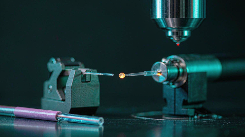
An ophthalmic laser probe is built from a length of low-OH silica fiber cleaved to 10–15 mm, polished successively on 15, 9, 3 and 0.3 µm lapping film, and then fused — briefly, in a fusion splicer — so that surface tension pulls the molten end into a glass microsphere. The radius of that sphere is not drawn on a print. It is set by the current the splicer applies and how long it applies it.
That one sentence contains the whole subject of this article. A laser fiber’s headline specification — core diameter, numerical aperture, wavelength range, power rating — is fixed when the preform is drawn, and nothing downstream changes it. But the part that actually touches the patient, the end face, is produced by a sequence of subtractive and thermal operations in which the geometry is an output of the process, not an input. This is why two suppliers can quote identical fiber and ship tips that behave differently, and why “how are laser fibers made” is really a question about the last few millimeters.
It starts with stripping, which is more consequential than it sounds
Before anything can be polished, the polymer coating has to come off, and the stripping step sets the ceiling on everything after it. Strip too little and residue contaminates the lapping film, which translates directly into an uneven end face and a depressed center. Strip too much and the exposed glass runs longer than the process needs, which means more unbuffered length to handle, more chance of a surface flaw, and more loss when the fiber is finally cut back.
The forces involved are standardized. Under IEC 60793-2-10, primary coating strippability is specified with an average strip force between 1.0 and 5.0 N and a peak force no higher than 8.9 N. That band is narrow for a reason: it is the window in which the coating separates cleanly from the cladding without the tool scoring the glass. For scale, the same standard sets a proof stress level of 0.69 GPa — about 1 % strain, or roughly 8.8 N of force — and a median tensile strength of at least 3.8 GPa for a half-meter specimen. Those strength figures describe intact, coated fiber. The moment the coating is stripped, a surface that was engineered to be flawless becomes exposed to tools, solvents and airborne contamination, and its strength becomes a function of how well the operator did.
This is the stage at which the fiber stops being a catalog item and becomes a workpiece. The starting material for everything described below is a plain bare fiber: cores from 200 to 1000 µm, flat or air-gap polished, rated to 30 W, transmitting from 400 to 2200 nm.
Cleaving is not cutting, it is starting a controlled crack
A fiber cleaver does not saw through glass. It scores the surface with a blade and then applies tension, so that a crack propagates across the end face perpendicular to the axis. Done well, the result is a mirror-flat facet with a few degrees of angle error and minimal chipping. Done badly, it leaves a hackle region, a lip, or a chipped edge.
It is tempting to treat cleaving as rough preparation that polishing will fix. Partly true, and partly a trap. Polishing corrects angle and flatness. It cannot correct a damaged layer without removing material, and removing material means the fiber gets shorter — which is not free, because every millimeter of length removed is a millimeter of loss budget spent before the fiber ever reaches a patient. Chipping that is 50 µm deep costs 50 µm of glass. In practice the sequence is arranged so that the coarsest stage removes the damage the cleaver left, and each subsequent stage removes only the damage the previous stage introduced.
Polishing is a converging sequence, not one operation
The four-stage film sequence in the opening paragraph — 15, then 9, then 3, then 0.3 µm — is not a generic recommendation, it is a working example of how the industry actually converges on a surface. Each stage removes the scratches the previous stage made, and each is finer than the one before by roughly a factor of three. The final film determines the finish, and if the final film is too coarse the end face ends up either undercut, with the fiber withdrawn behind the ferrule, or over-protruding, standing proud of it. Both are failures, and both come from a grade of abrasive, not from a skill level.
Two details of the medical case are worth separating from the telecom case, because they are frequently conflated.
The first is that an SMA-terminated medical fiber is designed with an intentional air gap. Fused silica reflects about 3.3 % at a glass-to-air interface, so two faces separated by an air gap cost roughly 0.29 dB in total. That is a deliberate trade: the air gap keeps high power away from the connector interface. A perfectly “coupled” contact would be optically tidier and thermally worse.
The second is that the distal emitting face has no communication-industry equivalent to copy from. The connector-side end face has a whole articulated standard vocabulary — curvature radius in the 7 to 25 mm range, apex offset, fiber height, 8° angle-polished contacts, interferometric geometry grading — and that vocabulary belongs to the proximal ferrule, not to the surface that emits into tissue. SMA medical terminations are typically flat-polished, have no equivalent geometric standard, and in high-power service are often held to tighter cosmetic requirements than telecom parts are. There is no shortcut here: the distal face is specified by the application, not by borrowing someone else’s table.
The same machinery makes three different geometries
Once the end face is flat and clean, geometry is applied. What is striking about the three main tip types is that they are not three different production lines — they are three different operations applied to the same prepared fiber, and each one is governed by one dominant process parameter.
| Tip geometry | Forming operation | The parameter that sets the geometry |
| Flat | Cleave, then staged lapping (15 → 9 → 3 → 0.3 µm) | Polish angle and final film grade |
| Ball | Arc, CO₂ laser or flame heating, or fusing a silica microsphere onto the cleaved end; surface tension rounds the molten tip | Splicer current and discharge duration |
| Conical | Etching in hydrofluoric acid | Etch time |
| Radial / diffusing | Emitting windows, ring markers, laser-welded cap; scattering layer | Window length and ring position |
| Side-firing | Angled polish plus a hermetically welded silica cap | Polish angle, set by the highest-order mode |
The ball tip is the clearest illustration of the principle. Two routes produce it. The end can be heated until it melts and pulls itself into a sphere, in which case the sphere is a mixture of core and cladding glass with no defined boundary to the transmission section; or a separately manufactured silica microsphere can be fused onto a cleaved end, preserving a clean interface. In both routes the radius comes out of the thermal budget. Commercial fusion splicers, using nothing more exotic than controlled arc discharge, have been shown to produce a roughly 300 µm sphere on a 125 µm single-mode fiber with 6 µm roundness error, and rotating the fiber between discharges suppresses the gravity-induced offset between the sphere center and the fiber axis to under 3 µm. That last number is the interesting one: without rotation, gravity alone puts the ball off-axis.
The focal properties follow from the ball, not the fiber. For a microsphere of radius R_s in a medium of index n₁, the focal length measured from the sphere center is n₁R_s/(n₂ − n₁), where n₂ is the sphere’s index. A designer who wants a specific working distance therefore specifies a sphere radius — and the shop delivers that radius by setting current and time. Which means the same physical parameter is an optical specification on one document and a process setting on another. For medical tips those settings, along with the sphere’s concentricity and the polish geometry below it, are established as customer-specific processing parameters rather than catalog defaults, which is why tip work sits under customization rather than under standard fiber.
Conical and radial geometries shift the parameter but not the logic. A cone is etched rather than ground, so etch time sets the cone angle, and a truncated or slanted cone is preferred over a sharp point because a sharp apex is fragile. A radial tip is assembled as much as formed: the emitting window is created, ring markers are placed to give the operator a visible datum for where emission begins, and the cap or sheath that defines the cylindrical emitting surface is laser-welded in place — the same “laser-welded to spec” process described on our own tip pages.
Where fabrication and failure are the same physics
Fused silica has a temperature ladder that matters here: a recommended service ceiling of about 1,050 °C in oxidizing conditions, the onset of surface devitrification — crystallization to cristobalite — at roughly 1,100 °C, a softening point near 1,585–1,600 °C, and melting at 1,713 °C. Between softening and melting, glass stops holding its shape and gravity and surface tension take over.
That is exactly how a ball tip is made. It is also exactly how a flat tip degrades in service: contamination on the end face carbonizes, the carbonized layer absorbs a large share of the delivered power, the end face overheats, and the tip softens and rounds off. The fabrication process and the failure mode are the same physical event, one under closed-loop control in a shop and one uncontrolled in a surgical field. That is not a rhetorical flourish; it is why process control is not bureaucratic overhead in this product category. A tip that is heated deliberately, for a measured number of milliseconds, at a measured current, becomes a lens. A tip that is heated accidentally becomes an unintended and unpredictable one.
Why inspection happens per unit, not per batch
Every unit that leaves a tip line is examined under a microscope before it ships, which sounds like overkill until you look at the dispersion.
Tip geometry varies more between individual fibers than the headline specifications suggest. In one study of 100 single-use holmium fibers recovered after clinical use, tip retraction averaged 1.664 mm with very wide scatter between individual fibers. Even within a single product family, the same nominal tip exists in several dimensional variants — a radial emitter is offered here at 400/800 µm and 600/950 µm without a ring marker, and at 400/730 µm and 600/750 µm with one. When the geometry itself is one of several near-identical variants, batch sampling cannot tell you what is in the box. Per-unit inspection covers what is inspectable: sphere radius or cone angle, window length and ring position, edge chipping, scratches, residual contamination, bubbles in the scattering layer, transmitted power, and beam cross-section.
It is worth being honest about the limit of the exercise. Inspection verifies that each tip left the factory matching its specification. It cannot verify what the tip will be after ten minutes of contact with a stone, a calcified plaque or a carbonized vein wall — that geometry is decided in the room, by the operator, using the fiber as delivered. The point of per-unit QC is that the starting geometry is known, so that any later change can be attributed to the case rather than to the shipment — which is also why per-unit measurement, rather than batch sampling, is written into our OEM process rather than offered as an option.
From an evaluation kit of one to a production run
The unusual commercial feature of tip fabrication is how little it costs to change your mind. Because the fiber itself is standard — the core, cladding, coating and jacket are not reinvented — a new tip geometry is a new set of process parameters rather than a new preform. That is the reason a minimum order quantity of one for an evaluation kit is workable rather than charitable: a single fiber with a modified end face can be made and shipped to a surgeon to evaluate in a real case, and the feedback that comes back is about the tip, not about a manufacturing commitment. The customization list is correspondingly long and correspondingly shallow — core diameter and numerical aperture, fiber length, tip geometry, connector type, jacketing and labeling, ring marking, and sterile packaging, all of which are documented on the customization page.
Scaling then becomes a question of reproducibility rather than capability. What makes a tip supplier useful at volume is not the ability to produce one perfect tip but the ability to produce the thousandth one with the same sphere radius, the same polish angle and the same window length as the first, backed by a process record and per-unit measurement. That is the substance of the OEM relationship we describe on our OEM partnerships page, and it is deliberately unglamorous: process documentation, first-article inspection, per-unit data, and a defined change-control path.
What the answer actually is
“How are laser fibers made” has a misleadingly simple shape as a question, because it suggests a single process. What it actually describes is a converging chain, in which each step narrows a tolerance: strip without damaging the surface, cleave without leaving damage behind, polish progressively so each stage erases the previous stage’s signature, then apply geometry with a thermal or chemical operation whose output is set by current, time or etch rate. The specification that reaches the customer is written as a geometry — flat, ball, radial, conical — but it was produced as a parameter. When a tip underperforms, the cause is usually visible in that chain long before it is visible in the clinic. A bare fiber is what you buy. An end face is what you are actually specifying.